Arduino Spi Beispiel

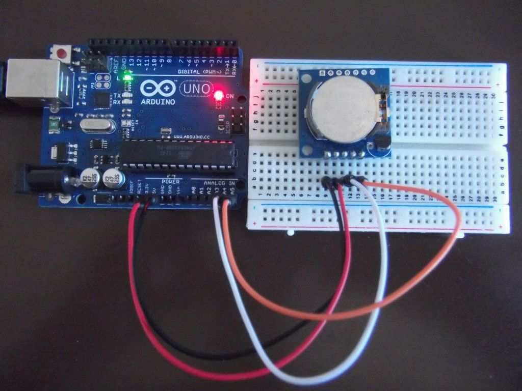
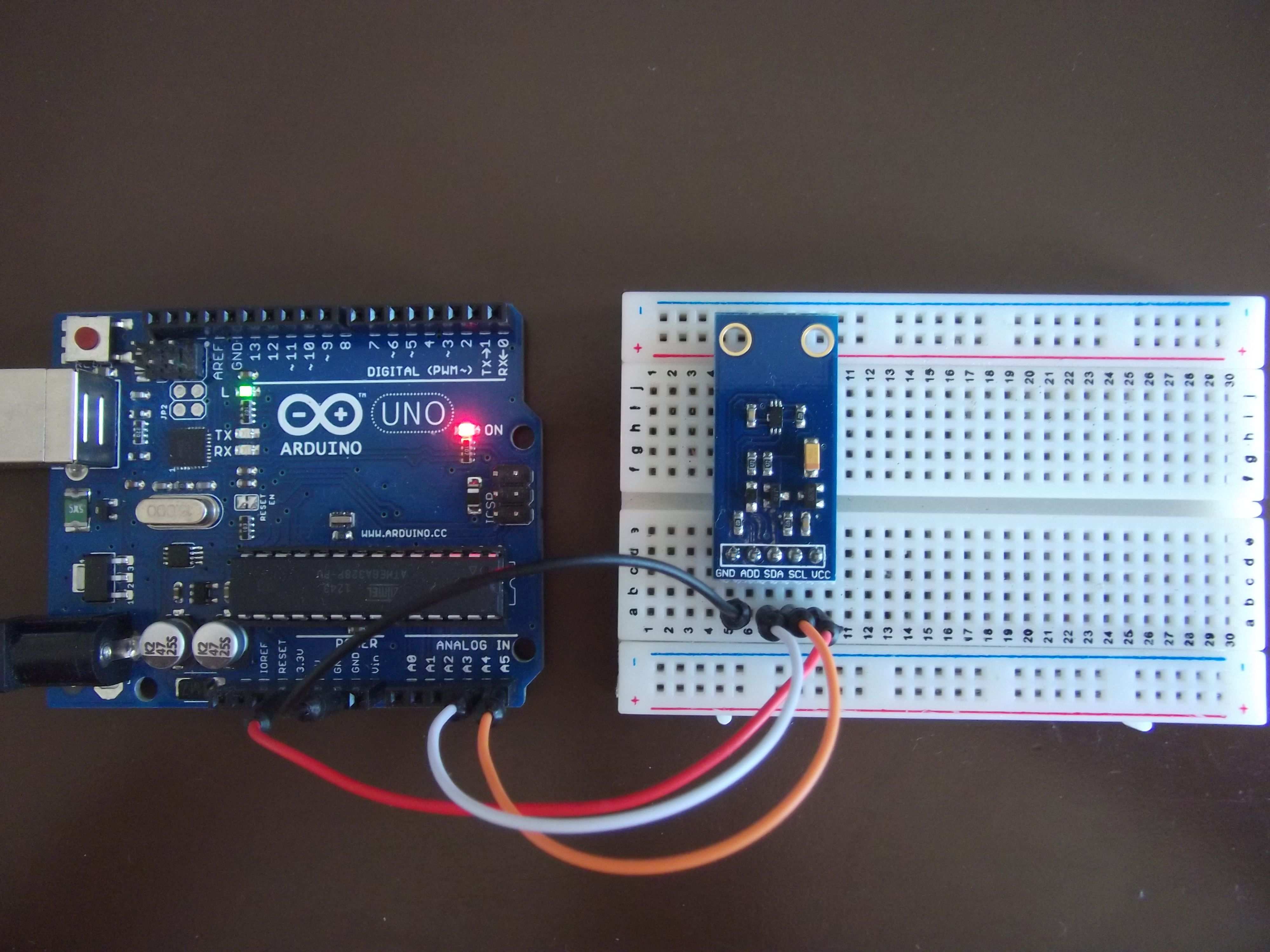
Examples barometric pressure sensor.
Arduino spi beispiel. Data travels back and forth along the mosi and miso lines between our arduino and the spi device. The default setting is spi clock div4 which sets the spi clock to one quarter the frequency of the system clock 4 mhz for the boards at 16 mhz. Now for the communication between this transmitter and receiver connect canh and canl pins of each mcp2515 module. 10 ss 11 mosi 12 miso 13 sck 5v falls erforderlich.
Make two such connections. Hence connect the spi pin i e. Verbinden sie zwei arduino unos mit den folgenden stiften die miteinander verbunden sind. Pin 12 sck.
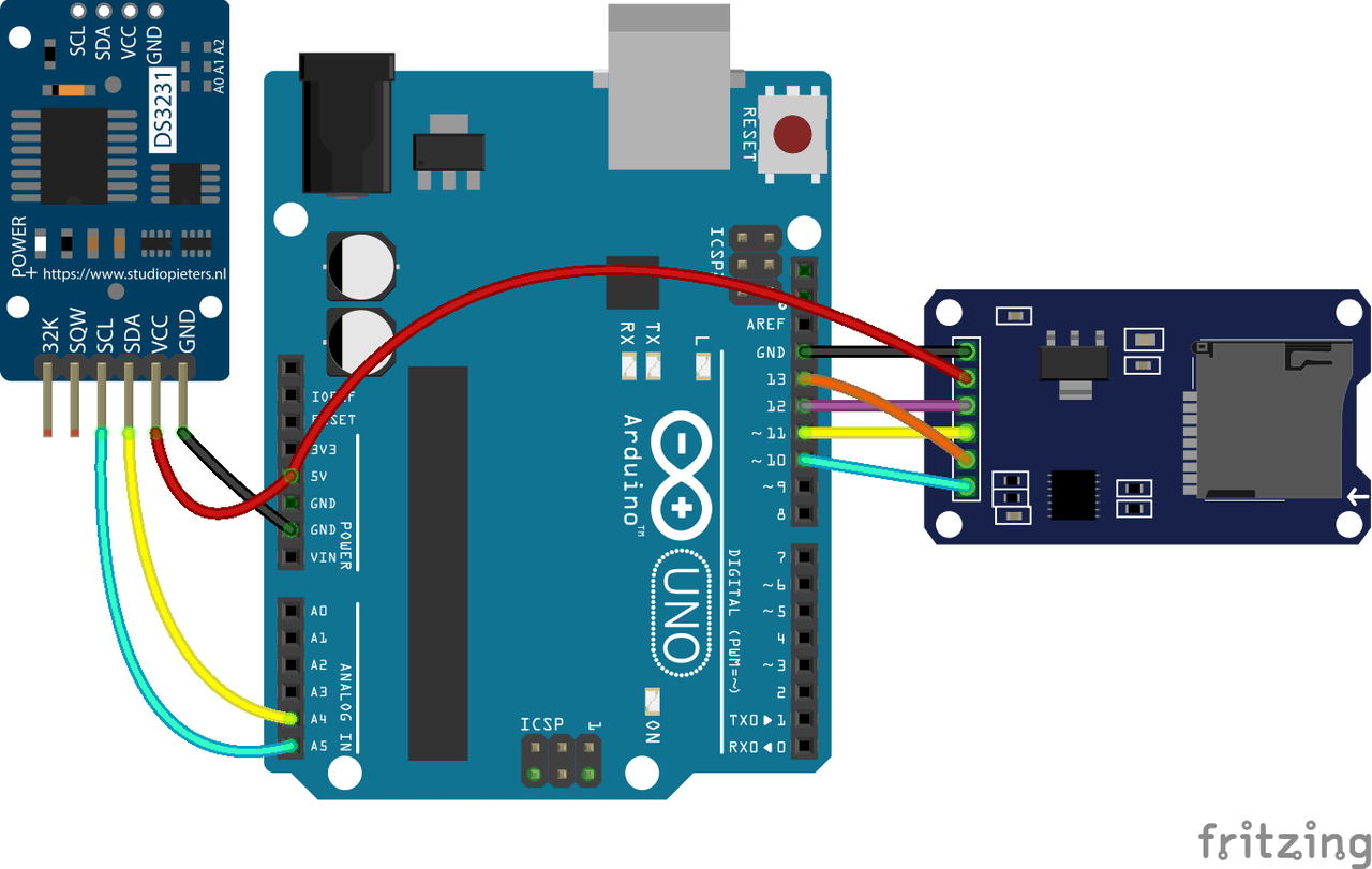
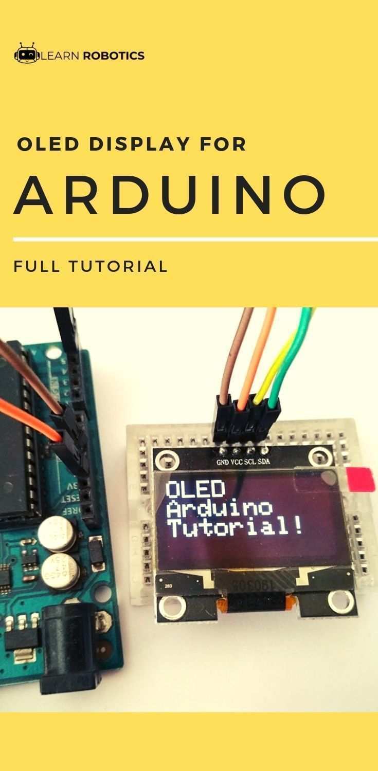
In diesem tutorial geht es darum wie verschiedene arduinos mikrocontroller oder sonstige geräte wie beispielsweise shields oder externer speicher mit einem arduino über das spi protokoll kommunizieren können. Starts serial communication at baud rate 115200. 20 is the sda while 21 is the scl. While the scl and sda pins of the oled display are connected with the arduino s analog pins a5 and a4 which are the i2c pins.
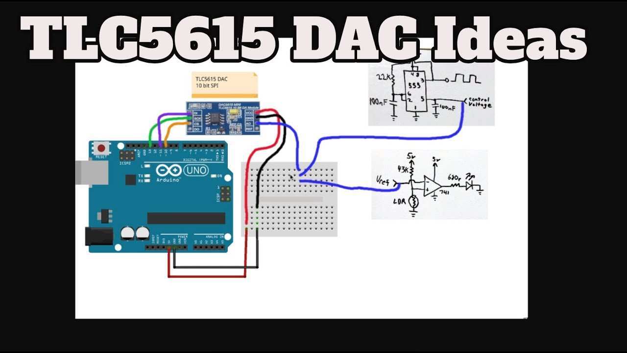
Void setup void serial begin 115200. See here for more information. So machen sie einen spi slave. Read air pressure and temperature from a sensor using the spi protocol.
Following is the diagrammatic representation of the connection between both the boards let us see examples of spi as master and spi as slave. Now we will connect two arduino uno boards together. The ground is common. The default value is 21 which sets the clock to 4 mhz like other arduino boards.
For example for one device the wiring would be. Arduino spi as master. Spi master arduino spi communication between two arduino circuit digest. You can control one or more devices with the spi bus.
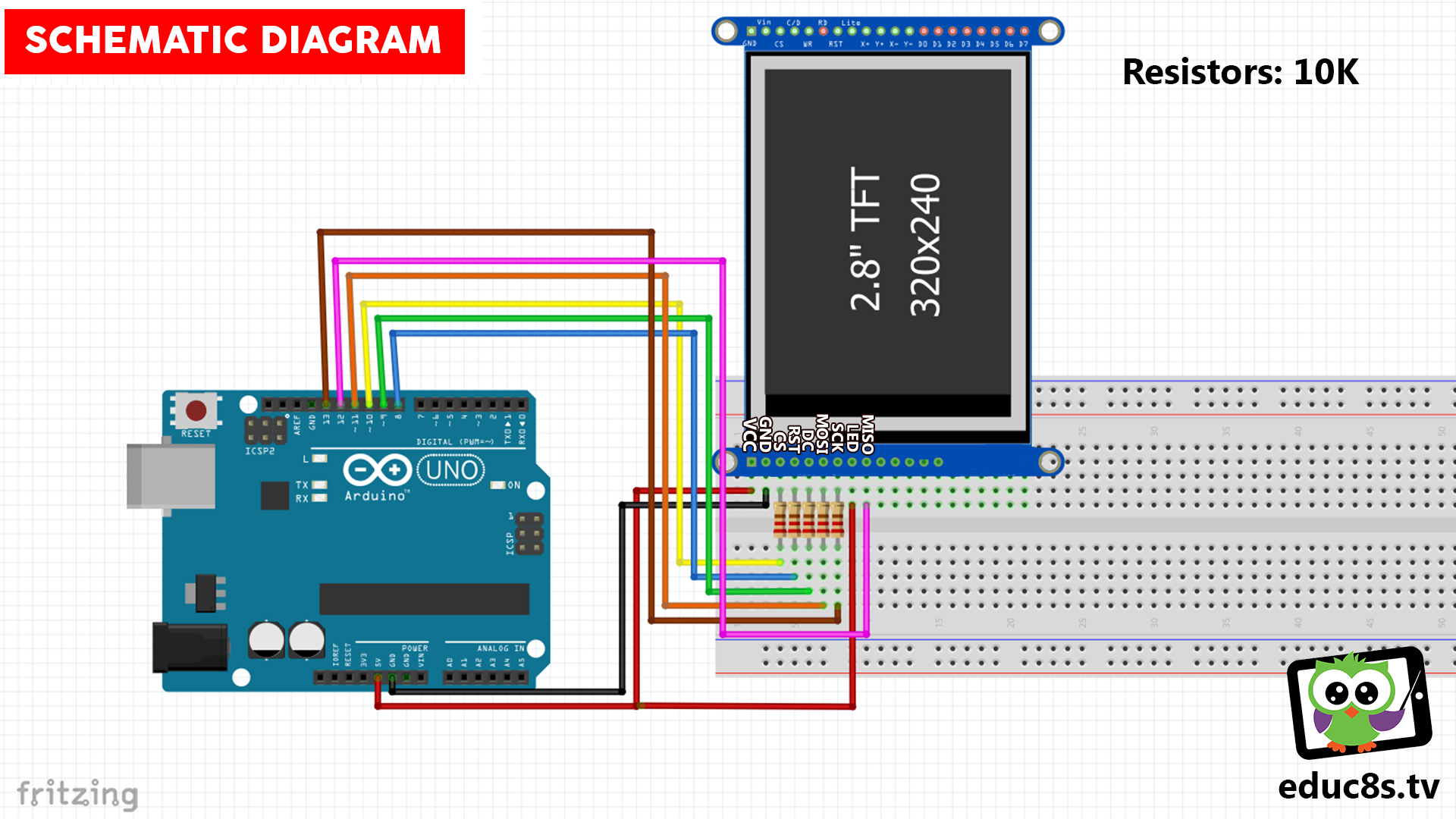
Das vorherige beispiel zeigt den arduino als master der daten an ein slave gerät sendet. Include spi h library for spi define led 7 define ipbutton 2 int buttonvalue. I interfaced my 128 64 i2c oled display with the arduino as per the circuit diagram already explained. If you are using an arduino leonardo the spi pins are on the icsp header pins.
One pair acts as a transmitter and the other as a receiver. If you are using arduino mega then connect these pins with 20 and 21. Pin 11 miso. Arduino due on the due the system clock can be divided by values from 1 to 255.
Das ist ähnlich wie i2c ein protokoll mit dem daten seriell übertragen werden. For example the arduino ethernet shield uses pin 4 to control the spi connection to the on board sd card and pin 10 to control the connection to the ethernet controller. Pin 10 mosi. Dieses beispiel zeigt wie der arduino ein sklave sein kann.